


 Spanish
 Russian
 Arabic

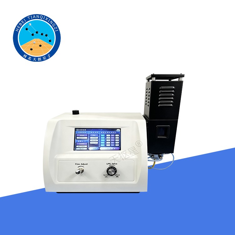

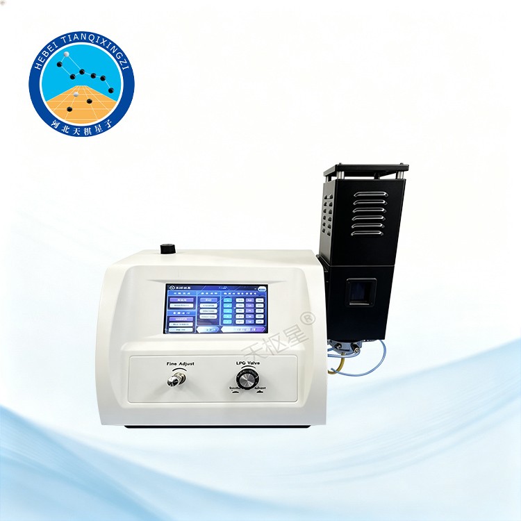
Products Description
The High-Precision Digital Flame Photometer is a laboratory instrument for rapid and accurate determination of sodium, potassium, lithium, calcium, and barium in various samples. Featuring digital display, multi-channel detection, stable performance, and convenient operation, it is widely used in soil, cement, glass, ceramics, fertilizers, food, pharmaceuticals, and clinical laboratory analysis.
High-Precision Digital Flame Photometer
Model: TDHYG-6400
I. Overview
The Flame Photometer is developed by our company in accordance with the Chinese industry standard JTG E40-2007, Highway Soil Test Regulations, including T0160-1993 “Determination of Sodium and Potassium Ions in Soluble Salts — Flame Photometry.”
According to the theory of atomic structure, electrons in the outer shell of an atom normally occupy specific energy levels. When exposed to the thermal energy provided by a flame, the electrons absorb energy and transition to higher excited energy levels. As the excited electrons return to their normal energy levels under the attraction of the atomic nucleus, they release energy in the form of light at characteristic wavelengths specific to each element. The qualitative and quantitative analysis of elements by measuring the wavelength and intensity of their characteristic emitted light is known as flame emission spectrometry. An analytical instrument based on this principle is called a flame photometer.
Reference Standards: ISO 9964-3:1993, ISO 7485:2000
II. Applications
The Flame Photometer can be used for the analysis and determination of sodium and potassium in a wide range of materials and samples:
1. Cement, Glass, Ceramics, and Refractory Materials: Analysis and determination of sodium and potassium content.
2. Agricultural Land and Soil: Agricultural soil surveys and determination of fertilizer nutrient content in soil.
3. Pharmaceutical and Food Industries: Product analysis and quality monitoring.
4. Medical and Clinical Testing: Determination of potassium and sodium concentrations in human serum and urine.
III. Main Technical Specifications
1. Detector: Silicon photocell
2. Spectral Separation: Interference color filter
3. Display: LCD digital display
4. Stability: When a standard solution is continuously introduced into the instrument, the maximum relative variation in the instrument reading within 15 seconds is ≤3%. When measurements are taken once per minute for a total of 6 measurements, the maximum relative variation in the instrument reading is ≤15%.
5. Repeatability: ≤3%
6. Linearity Error:
K: ≤0.005 mmol/L
Na: ≤mmol/L
7. Response Time: <8 s
8. Sample Aspiration Rate: <6 mL/min
9. Measurement Range:
Na: 0–100 ppm; K: 0–100 ppm; Li: 0–100 ppm; Ca: 0–1000 ppm; Ba: 0–3000 ppm
10. Detection Limit:
Na: 0.01 ppm; K: 0.01 ppm; Li: 0.025 ppm; Ca: 0.1 ppm; Ba: 10 ppm
IV. Structural Features
1. Five Optical Filters and Five Detection Channels: Equipped with optical filters for Na, K, Li, Ca, and Ba, providing five detection channels. Up to three elements can be detected simultaneously, with the concentrations of all three elements displayed at the same time.
2. Digital Keypad Touch Panel: Equipped with a digital keypad touch panel for convenient operation and parameter setting.
3. Single-Point Calibration: Supports single-point calibration, and the instrument can store calibration curves for subsequent use.
4. RS232 Interface: Equipped with an RS232 interface for connection to a computer or printer.
5. Moisture Separator: Equipped with a moisture separator to help remove moisture from the sample gas path and improve measurement stability.
V. Normal Operating Conditions
a) Ambient Temperature: +10°C to +35°C
b) Relative Humidity: ≤85%
c) The instrument should be placed horizontally on a stable, vibration-free workbench. Avoid direct exposure to strong light, strong electric or magnetic field interference, excessive airflow, and any vibration that may affect operation.
d) The installation site should be free from flammable, explosive, and corrosive gases, and suitable fire-extinguishing equipment should be readily available.
e) Power Supply: 220 V ±22 V AC, 50 Hz ±1 Hz, with a reliable protective grounding connection.
f) Rated Power: 250 W
g) The user should provide clean, impurity-free liquefied petroleum gas (LPG) or propane with stable combustion performance.
VI. Dimensions, Weight, and Standard Configuration
1. Dimensions: 440 × 310 × 500 mm
2. Weight: 12.5 kg
3. Standard Configuration: Includes the main unit, air compressor, accessories, spare parts, and other necessary components.
VII. Instrument Structure
1. Gas Circuit System
Before shipment, each instrument is subjected to strict testing to ensure proper operation. The rear panel of the instrument is equipped with gas inlet connections. The air inlet is connected to the air compressor, while the liquefied gas inlet is connected to the liquefied gas cylinder.
The compressed air from the air compressor passes through a filter pressure-reducing valve, and the pressure is controlled within 0.12–0.20 MPa to provide the air supply required for sample aspiration.
The liquefied gas flow is regulated by a needle valve and then enters the atomization chamber, where it mixes with the sample before entering the combustion chamber for stable combustion.
2. Measurement System
When the sample is introduced into the combustion chamber, the elements present in the sample emit their characteristic spectral lines. After passing through the interference filter, stray light is effectively eliminated, allowing light at the selected wavelength to reach the detector. The silicon photocell receives the emitted light and converts its intensity into an electrical signal. The signal is then amplified and processed, and the measurement result is displayed on the LCD screen.
VIII. Maintenance and Servicing
1. Cleaning After Each Test: After completing each test, continuously aspirate and pass distilled water or anhydrous ethanol through the instrument for 5 minutes to thoroughly clean the atomizer chamber and prevent residual sample buildup.
2. Draining the Filter Pressure-Reducing Valve: During operation of the air compressor, moisture in the compressed air may condense and accumulate inside the filter pressure-reducing valve. If water accumulates over an extended period, it may affect the normal operation of the instrument. After approximately one week of use, raise the instrument slightly and turn the drain valve of the filter pressure-reducing valve located at the rear left side of the instrument. The accumulated water will be automatically discharged under compressed-air pressure. After the water has been completely drained, turn the valve in the opposite direction to close it securely.
3. Draining the Air Compressor: During operation of the air compressor, moisture in the air may condense and accumulate at the bottom of the compressor. Long-term accumulation of water may affect normal operation. After approximately one week of use, raise the air compressor slightly and turn the drain valve located underneath the compressor. The accumulated water will be automatically discharged under compressed-air pressure. After the water has been completely drained, turn the valve in the opposite direction to close it securely.
