


Products Description
The machine adopts a micro-electric hydraulic loading system, utilizes a load sensor for force measurement, and features a digital display for test results. It is an essential testing and inspection instrument for construction, building materials, highways, bridges, and other engineering applications.
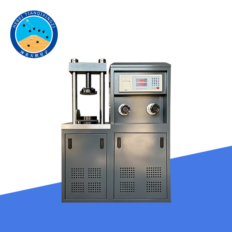
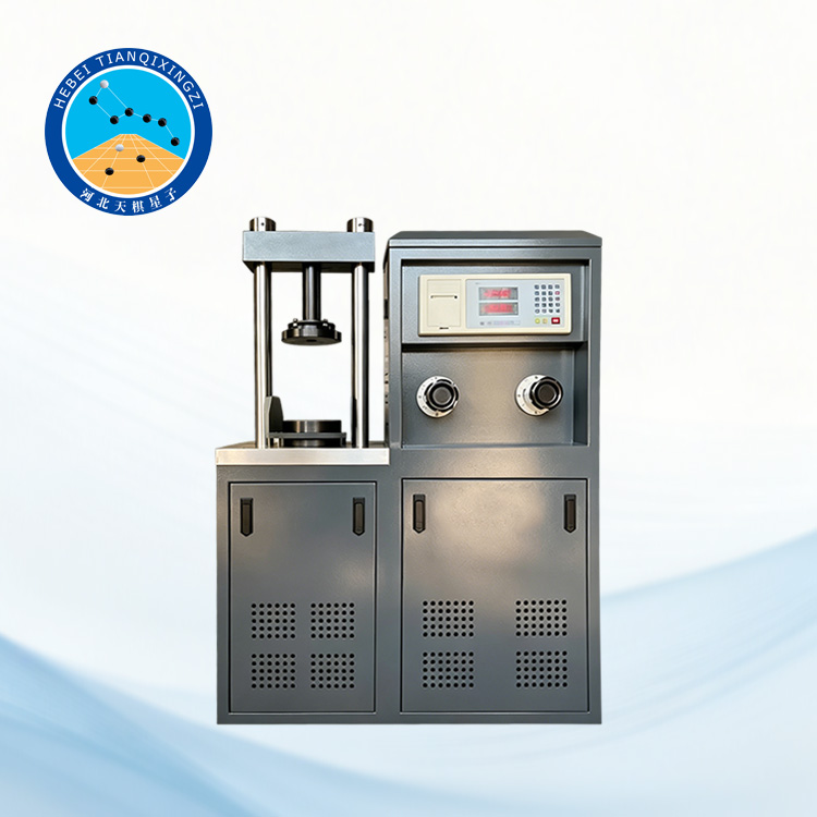
Electro-Hydraulic Concrete Flexural and Compression Testing Machine
Model:TDYE-300
I. Product Introduction
This testing machine is designed for determining the flexural strength of concrete specimens with dimensions of 150 × 150 × 550 mm and 100 × 100 × 400 mm, as well as the compressive strength of cement, mortar, and other building materials.
The machine complies with GB/T 50081-2002 "Standard for Test Methods of Mechanical Properties of Ordinary Concrete". Loading speed is manually controlled and indicated by a dedicated loading rate display device. During testing, the load can be applied uniformly and continuously. The machine is also equipped with a flexural testing fixture that applies two equal loads simultaneously at the one-third points of the specimen span, ensuring accurate flexural strength testing.
Reference / Applicable Standards: ASTM C39/C39M, EN 12390-3, BS EN 12390-3, GB/T 50081-2002
II. Structural Principle
This testing machine is composed of a frame, oil pump, oil supply valve, oil return valve, and control/display unit. All components are installed on the lower cabinet to form an integrated structure.According to user requirements, the machine can also be optionally equipped with a flexural testing fixture and a splitting tensile fixture, one set each.
1. The frame assembly consists of the lower cabinet (1) and the crossbeam (6), which are connected by two upright columns (4) to form a rigid integral structure. Both the upper and lower loading platens are processed and ground flat. The lower platen is marked with a Φ101 mm center circle line, which helps the operator properly align the specimen and compression fixture during placement to ensure correct centering.
2. Five-Plunger Oil Pump
This machine adopts a five-plunger axial high-pressure oil pump. The plungers and cylinder sleeves inside the pump body are made of high-quality alloy steel, which has undergone heat treatment and precision grinding to ensure durability and high performance.
3. Oil Supply Valve
The oil supply valve is a split-type flow regulating valve, composed of a variable throttle valve and a constant differential pressure reducing valve connected in parallel.
4. Oil Return Buffer Valve
The oil return buffer valve consists of an unloading switch and an oil return throttle valve. Its function is to release the load and rapidly reduce the hydraulic pressure in the working cylinder. During operation, the operator opens the oil return valve for unloading, and the high-pressure oil in the cylinder flows back to the oil tank.
5. Control System: This force measuring instrument processes the measured force data via a microcontroller according to user requirements, enabling printing, data storage, network connectivity, and data transmission over a network.
III. Technical Parameters
Maximum Load: 300 KN
Relative Error of Indication: ±1%
Relative Error of Test Force Indication: ±1%
Diameter of Bending Roller: φ30
Upper flexural roller center distance: 100 / 150 mm
Lower flexural roller center distance: 300 / 450 mm
Pressure platen diameter: Ø160 mm
Clear distance between upper and lower platens: 180 mm
Piston diameter × maximum stroke: Ø125 × 50 mm
Motor power: 0.75 kW
Overall dimensions: 870 × 390 × 1210 mm
Net weight: 550 kg
IV. Installation and Commissioning
1. The testing machine should be installed indoors where the room temperature is between 10°C and 35°C, and the relative humidity does not exceed 80%.
2. The installation site should be properly selected to facilitate operation, maintenance, and servicing. The foundation must be solid and reliable, and the anchor bolts should be properly aligned with the base.
3. Leveling adjustment of the machine body:Use a 0.1/1000 precision spirit level to measure the working cylinder platform surface. Adjust both longitudinal and transverse levels within ±1 division. If the deviation exceeds ±1 division, shim plates can be placed under the base for correction, and then tighten the anchor nuts.
4. Electrical specification:The power supply is three-phase, 50 Hz AC, 380 V. The combined switch H serves as the main power switch.
V. Instructions for Use
1. When the power is on, the display shows year, month, day, hour, and minute. Press the "Reset" button to enter the test waiting state.
2. Press the "Start" button; the motor will start running, and the system will enter the test state. Place the test block, open the oil supply valve, and the breaking point will be automatically maintained. If the motor does not stop, the return oil valve must be opened to unload the load.
3. When preparing the second test block, press the "Start" button again to re-enter the test state.
Note: Pressing the "Stop" button at any state will stop the motor and exit the test state.
