


 Spanish
 Russian
 Arabic

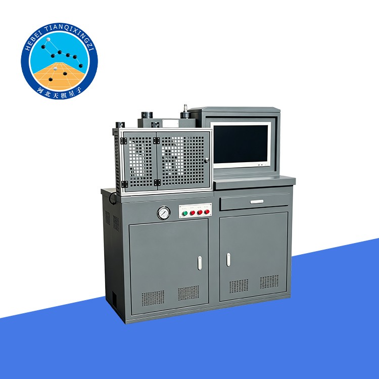

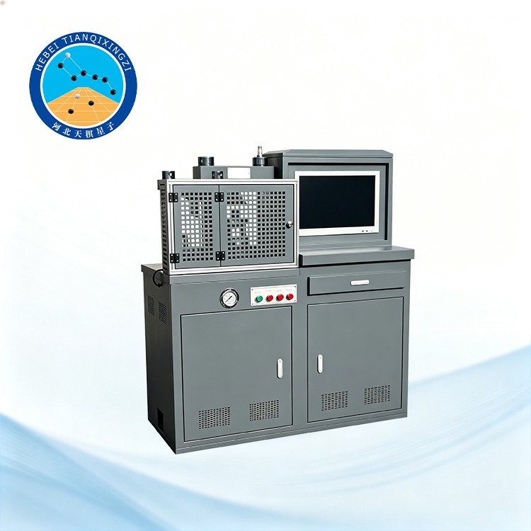
Products Description
The Digital Cement Mortar Compression Testing Machine is designed to determine the flexural and compressive strength of cement mortar specimens. With precise electronic control and reliable force measurement, it is suitable for cement plants, construction material laboratories, research institutions, and quality control applications.
Digital Cement Mortar Compression Testing Machine
Model: TDYE-300S
I. Operating Conditions
1. Ambient Temperature: 0–40°C
2. Relative Humidity: ≤90% RH
3. Power Supply: 220 V ±10%, 50 Hz
4. Safety Performance: Complies with the requirements of GB/T 2611-2022
II. Functions and Components
1. Instrument Function:
The machine is mainly designed for determining the flexural and compressive strength of cement mortar specimens. It complies with the requirements of JC/T 960-2022, Automatic Compression Testing Machine for Cement Mortar Strength, with reference to ISO 679:2009 and EN 196-1:2016.
2. Main Components:
1 × Main Testing Machine
1 × Controller with 17-inch touchscreen terminal
1 × Output Terminal
2 × Flexural Testing Fixtures
2 × Compression Testing Fixtures
3. Control Terminal:
17-inch touchscreen display
J1800 processor
4 GB RAM + 128 GB storage
2 × Ethernet ports + 2 × serial ports
4. Output Terminal:
Equipped with printing, copying, and scanning functions. The laser printer supports automatic duplex printing as well as both wired and wireless printing, with black-and-white output.
5. Testing Fixtures:
Includes 2 flexural testing fixtures and 2 compression testing fixtures, complying with the requirements of GB/T 17671-2021.
III. Technical Specifications
1. Test Force:
Compression: ≥300 kN
Flexure: ≥10 kN
2. Testing Machine Accuracy Class: 0.5
3. Force Measurement Range: 2%–100% FS
4. Relative Error of Indicated Test Force: ±0.5%
5. Loading Rate:
Compression: 0.1–25 kN/s
Flexure: ≥50 N/s
6. Loading Rate Error: ±5%
7. Distance Between Upper and Lower Platens:
Compression: 0–260 mm
Flexure: 0–200 mm
8. Loading Plate Dimensions:
Compression: Φ200 mm ±5 mm
Flexure: 80 mm ±5 mm × 150 mm ±5 mm
9. Stroke:
Compression: ≥100 mm
Flexure: ≥80 mm
10. Control Mode: Electronic
11. Motor Power: ≥0.75 kW
12. Main Machine Weight: Approx. 500 kg
IV. Main Structure and Working Principle
The testing machine mainly consists of a machine frame, hydraulic PID control system, microcomputer-based measurement, display and printing system, and electrical system.
1. Machine Body
The machine body is an integrated structure consisting of a base, crosshead, supports, and two columns. The working cylinder is fixed to the base, and its piston has a maximum upward stroke of 80 mm. A dust cover is installed on the plunger to prevent dust from entering the cylinder when the piston moves upward.
The working cylinder and piston are equipped with a combined sealing system. A dedicated oil overflow hole is provided on the inner wall of the cylinder. This design minimizes the friction between the working cylinder and piston, thereby helping ensure the accuracy of the testing machine.
The circular scale marking (Φ100 mm) on the lower platen helps the operator locate the center when positioning the specimen and compression fixture.
2. Hydraulic Operating System
The hydraulic control unit mainly consists of an oil tank, oil pump, oil filter, proportional valve assembly, two-position four-way valve, and safety valve, all of which are mounted on the machine body.
The oil pump is a direct-shaft five-plunger pump. During loading, the proportional valve controls the hydraulic cylinder pressure and loading rate to provide stable and precise force application.
3. Force Measurement System
The machine uses a high-precision load cell with an accuracy of ±0.05%. The sensor signal is amplified through the PCI board and amplifier board, and the resulting control signal is used to regulate the proportional valve during loading and the two-position four-way valve during unloading.
